What Are Stick Welding Sticks and How Do You Choose Them?
Stick Welding Sticks are consumable electrodes that create the arc and provide filler metal during shielded metal arc welding. Their coatings also help protect the molten weld from contamination. Choosing a rod is not just a matter of picking a number from a shelf. The right option depends on the base metal, joint position, material thickness, power source, and the work environment.
Electrode labels offer useful clues. For example, the AWS classification E6011 or E7018 describes properties such as tensile strength and usable welding positions. These details matter when repairing a farm gate, joining clean plate in a shop, or working outdoors where wind can disrupt other processes. Check the electrode manufacturer’s instructions and your welding machine’s manual for compatible current and polarity. A rod that runs smoothly on one setup may behave poorly on another.
Small choices show up in the bead. A damp electrode may cause porosity, while excessive amperage can leave undercut along the plate edge. Keep rods clean and dry as their packaging directs. Practice on scrap of similar thickness before welding a critical joint. It helps. There is no universal “best” stick, and classification alone cannot guarantee a sound weld. Fit, preparation, technique, and inspection still count; that part is easy to underestimate. This guide explains common electrode types, how to read their classifications, and how to match them to practical welding conditions. When a joint is safety-critical, follow qualified procedures and seek an experienced welding professional’s review.
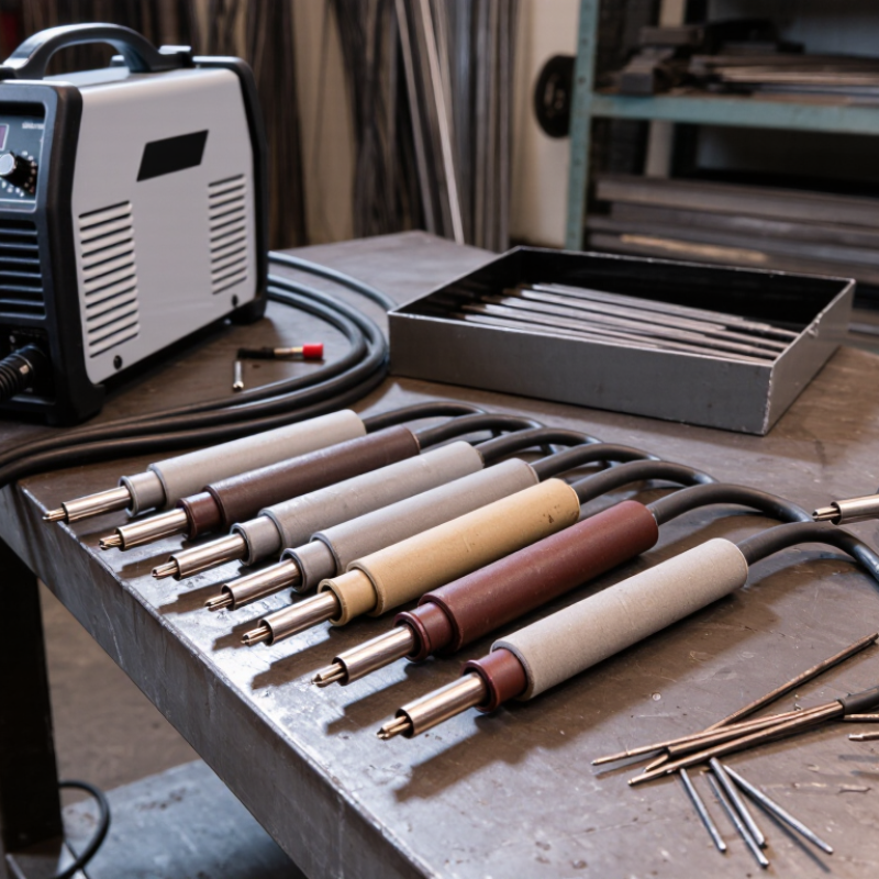
What Stick Welding Sticks Are and How They Work
Stick welding sticks, also called covered electrodes, carry current and supply filler metal to the joint. An arc forms between the rod tip and the workpiece, melting both the rod’s metal core and the edge of the base metal. The coating breaks down in the heat, creating shielding gases and a layer of slag over the cooling weld. That protection matters: an exposed molten puddle can react with air and develop defects. The rod is consumed as you weld. Keep the arc short.
AWS A5.1/A5.1M classification data makes the markings useful. In E6013, “E” means electrode, “60” identifies a minimum deposited-weld-metal tensile strength of 60,000 psi under specification testing, and “1” indicates all-position use. The final digit describes the coating and usable current characteristics. In practice, match the electrode to the base metal, joint position, thickness, and available AC or DC power. A thin sheet may burn through with an overly aggressive setup; a heavy plate may need more deposition. The coating’s slag can also obscure the bead, so inspect the cleaned weld rather than judging it through the residue. Even a correctly classified rod can perform poorly if damp, badly stored, or run with an unstable arc.
What Are Stick Welding Sticks and How Do You Choose Them?
Minimum Tensile Strength by Electrode Classification
Stick welding sticks are consumable electrodes: their metal cores melt to form the weld, while their flux coatings help shield the arc and create protective slag. In these four-digit classifications, the first two digits indicate minimum tensile strength in thousands of pounds per square inch (ksi). Choose an electrode based on the base metal, required strength, welding position, and the power source available.
How Electrode Coatings and Classifications Differ
Stick electrodes differ most visibly at the coating: it controls arc stability, slag release, penetration, and moisture sensitivity. The American Welding Society’s AWS A5.1/A5.1M specification encodes key properties in the electrode classification. In E7018, “70” indicates a minimum tensile strength of 70,000 psi, while “1” identifies all-position use. The final digits identify coating and current characteristics. E6010 uses a cellulose-sodium coating and typically runs on direct current electrode positive; E6011’s cellulose-potassium coating also supports alternating current. Small code, major difference.
Low-hydrogen E7018 electrodes help limit hydrogen-related cracking in suitable steels, but their coating must stay dry. A damp rod can cause porosity or unreliable weld quality. Cellulose-coated types often produce a forceful arc and deeper penetration, useful on rusty or less-clean surfaces, though they can create more spatter. Rutile-coated E6013 generally offers a smoother arc and easier slag removal on lighter work. Convenient, but not universal.
Match the rod to base metal, joint position, thickness, and the power source—not just the strength number. AWS classification values are useful starting data, not a promise of identical results across every job. A chart can make selection look simpler than it is. Keep a few labeled samples, then inspect bead shape, slag release, and fusion on scrap of the same thickness. That check is easy to skip. It should not be.
What the Numbers and Letters on a Stick Electrode Mean
A stick electrode’s printed code gives useful clues before the arc starts. In E6013, “E” means electrode, and “60” indicates a minimum tensile strength of 60,000 pounds per square inch. The third character, “1,” identifies an all-position electrode. That matters when a repair moves from a flat plate to a vertical joint. The final “3” describes the coating and compatible current category. Read the full classification, not just the strength number.
E7018 follows the same pattern: “70” indicates 70,000 psi tensile strength, “1” means all-position, and “8” identifies a low-hydrogen iron-powder coating and its current class. Low-hydrogen rods need careful, dry storage; a damp box can undermine their purpose. Some electrodes also carry suffixes, such as H4 or R, that describe additional hydrogen or moisture-resistance testing. Check the package or data sheet for exact polarity and operating limits, since similar-looking rods can behave differently. A small detail, but an easy one to miss. Choose by base metal, joint position, power source, and welding procedure—not by the largest strength number alone.
How to Choose an Electrode for Your Metal and Welding Position
Stick electrodes are selected by matching the rod to the base metal, its thickness, and the welding position.
For mild steel, classifications such as E6013 and E7018 suit different conditions. E6013 often provides a steady arc on clean steel, while low-hydrogen E7018 requires dry storage and careful handling. Stainless steel or cast iron needs an electrode made for that alloy; appearance alone is not a reliable guide. Check the base-metal specification when strength or service conditions matter. Fit matters.
Position can narrow your options. In common AWS electrode codes, the third digit indicates usable positions: 1 generally means all positions, while 2 is for flat and horizontal welding. Check the full classification and product data sheet, since suffixes and specific formulations can affect use.
Choose a rod diameter suited to the metal: a large rod can burn through thin sheet, while a small one may make thicker joints slow to fill. Confirm that your power source supports the electrode’s AC or DC requirements, and set amperage within its stated range. Test on scrap of similar thickness.
I still find position easy to overlook when choosing rods, especially for overhead work.
How to Match Electrode Size and Current to the Job
Choosing a stick electrode starts with the steel thickness and joint, not just the welder’s maximum output. A 3/32-inch rod can suit thinner plate and tighter joints; a 1/8-inch rod deposits more metal but needs more heat and room to work. On many common electrodes, a 1/8-inch size runs somewhere around 90–140 amps. That is only a starting range. Electrode type, polarity, position, and manufacturer guidance can shift it.
Check the electrode package and machine manual, then make a short test bead on scrap of similar thickness. The arc should stay steady, and the puddle should move without burning through or leaving a tall, rope-like bead. If the rod sticks repeatedly, increase current slightly or check your arc length and ground connection. If the plate edges melt away, reduce current or move faster. Small changes matter. Overhead or vertical welds often call for a smaller rod or lower current than a flat weld. I used to blame every rough bead on the amperage; that was not always fair. Travel speed and technique can be the real problem, and a quick test does not replace a sound fit-up.
What Are Stick Welding Sticks and How Do You Choose Them? — How to Match Electrode Size and Current to the Job | Electrode Classification | Diameter | Typical Current Range | Common Uses and Selection Notes |
| E6010 | 3/32 in (2.4 mm) | 40–85 A | Deep-penetrating electrode for root passes, pipe, and outdoor work. Usually requires a DC electrode-positive (DCEP) power source. |
| E6010 | 1/8 in (3.2 mm) | 75–125 A | Useful for faster deposition on heavier material and open-root joints. Check that the machine supports the electrode’s current and polarity requirements. |
| E6011 | 3/32 in (2.4 mm) | 40–85 A | General-purpose, penetrating electrode that can run on AC or DC. Often selected for rusty or less-than-perfectly clean steel and outdoor repairs. |
| E6011 | 1/8 in (3.2 mm) | 75–125 A | Suitable for repair work and thicker sections. Its forceful arc can help with less-clean surfaces, but proper joint preparation is still recommended. |
| E6013 | 3/32 in (2.4 mm) | 40–90 A | Smooth, relatively easy-to-control arc for light fabrication, thin steel, and general maintenance. Works with AC or DC on many products. |
| E6013 | 1/8 in (3.2 mm) | 80–130 A | A versatile choice for general mild-steel work. The softer arc and manageable slag can suit beginner practice and moderate-thickness material. |
| E7018 | 3/32 in (2.4 mm) | 70–110 A | Low-hydrogen electrode for strong, quality welds on clean steel. Often used for structural work; follow storage and handling instructions to keep it dry. |
| E7018 | 1/8 in (3.2 mm) | 90–150 A | Common size for structural and general fabrication work. Confirm the required welding position and polarity on the electrode packaging. |
| E7018 | 5/32 in (4.0 mm) | 140–210 A | Higher deposition rate for thicker sections and larger welds. Requires a power source capable of sustaining the selected current. |
| E7024 | 1/8 in (3.2 mm) | 100–160 A | High-deposition electrode intended mainly for flat and horizontal fillet welds. Not a general choice for vertical or overhead welding. |
| E7024 | 5/32 in (4.0 mm) | 160–240 A | Designed for fast welding on suitable flat or horizontal joints. Best used where the workpiece and position allow a large, fluid weld pool. |
Current ranges are typical starting points, not universal settings. The correct amperage varies with the specific electrode, manufacturer, welding position, joint design, and power source. Use the range printed on the electrode packaging and adjust based on arc stability, penetration, and weld-pool control.
Quick Selection Guide | Job Factor | Practical Starting Point | What to Check |
| Material thickness | Use a smaller diameter electrode for thinner material and a larger diameter for thicker sections. | A large electrode can put too much heat into thin metal; a small one may require more passes on thick material. |
| Welding position | Choose an electrode approved for the position: flat, horizontal, vertical, or overhead. | Some high-deposition electrodes are limited to flat and horizontal work. Follow the classification and product instructions. |
| Surface condition | For less-clean steel, a suitable cellulose-type electrode may be more forgiving; clean the joint whenever possible. | Rust, paint, oil, and moisture can affect weld quality and may create hazardous fumes. |
| Power source and polarity | Match the electrode to the machine’s available AC or DC output and polarity. | Electrode requirements differ; consult the packaging or a qualified welding procedure. |
| Amperage adjustment | Start within the recommended range and make small adjustments as needed. | Too little current can cause sticking and poor fusion; too much can cause excessive spatter, undercut, or burn-through. |
